
Categories
7FA
Borescope
Gas Turbine Inspection
Non Destructive Testing
Secure Multi Party Computation
The Compiler
Uncategorized
Book Your
Consultation

A pulled liner or a stack of borescope images looks like scrap metal to an untrained eye. To an engineer who knows what to look for, it’s a component communicating exactly what the turbine has been through, and the difference between reading that message correctly and misreading it is the difference between a scheduled repair and an unplanned outage.
Every crack, coating loss, and bowed airfoil is hot gas path damage, and each one points to something specific about combustion dynamics, load cycling, or fuel quality. A professional hot gas path inspection exists to translate those signals before they become failures.
This article walks through what combustion liners, transition pieces, nozzles, vanes, and blades reveal when read correctly, and how to turn those findings into a defensible repair, replace, or run decision.
Key Takeaways
- Damage patterns on hot gas path components reveal root cause, severity, and remaining life, not just cosmetic wear.
- Combustion liners, transition pieces, nozzles, vanes, and blades each fail in distinct, diagnosable ways tied to thermal, mechanical, or chemical stress.
- Hot Gas Path Inspections (HGPIs) are scheduled by fired hours and starts. They are a different scope of work than a full major overhaul.
- Findings across multiple components often point to one systemic root cause, such as fuel quality or combustion dynamics, rather than five unrelated part failures.
- Confirmed diagnostics using NDT and clear inspection reporting are what turn a borescope finding into a confident repair decision.
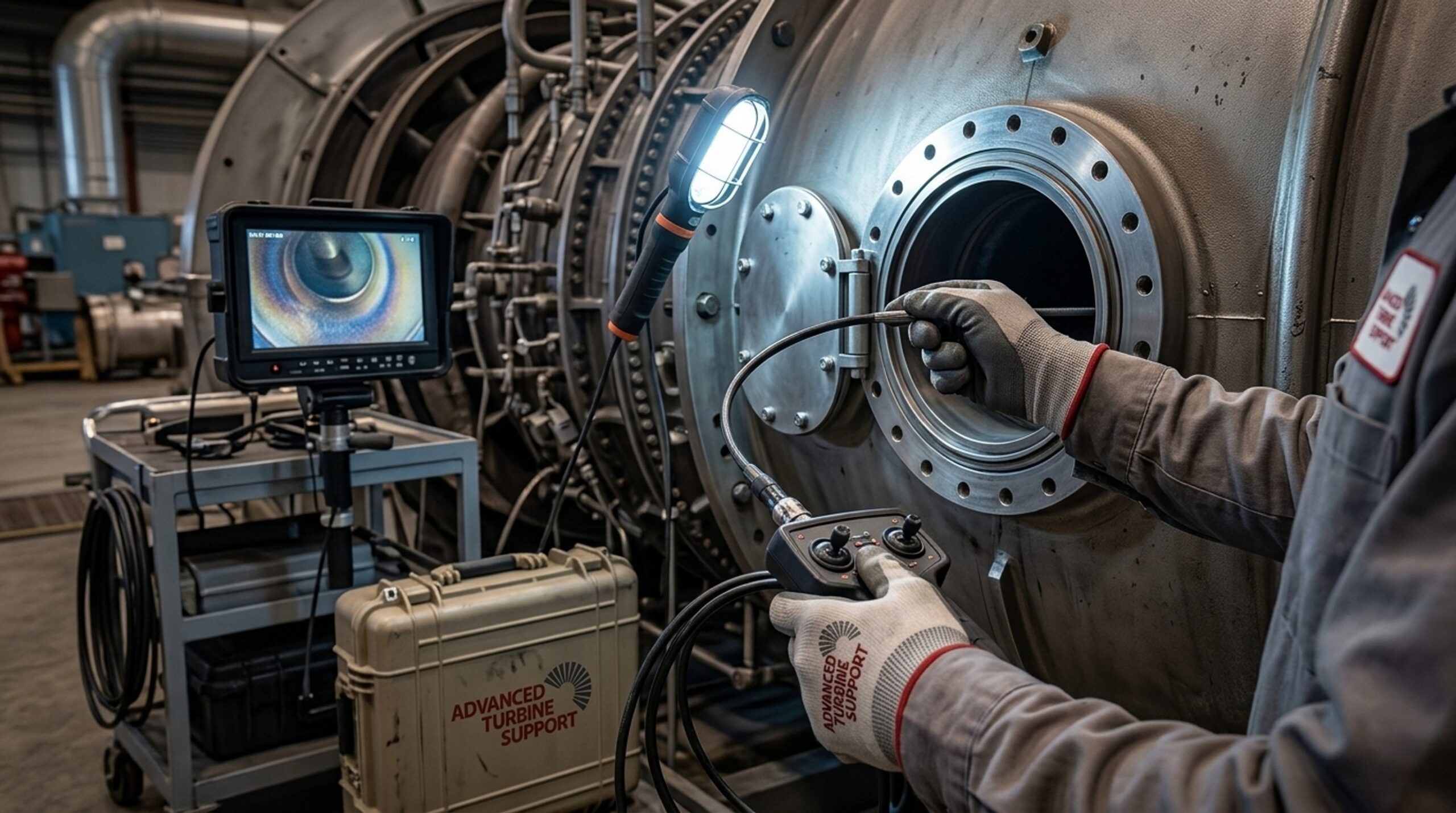
What Damage Patterns on Hot Gas Path Components Reveal During a Gas Turbine Inspection
Damage patterns on hot gas path components reveal the root cause of distress, its severity relative to remaining service margin, and the component’s remaining useful life. Each mark on gas turbine components is part of a diagnostic readout across the entire gas turbine hot gas path. Thermal, mechanical, and chemical evidence, read together, form one clear picture of turbine health.
Reading that picture correctly is what separates a planned repair from an unplanned outage. Research on gas turbine hot gas path degradation assessment (ResearchGate, Degradation Assessment of Gas Turbine Hot Gas Path Components) confirms that damage progression is measurable and predictable when tracked consistently across inspection cycles, not treated as a one-time snapshot. Many forced shutdowns trace back to a pattern that appeared during a prior inspection but got read as minor. Applying consistent inspection methods across every outage is what makes it possible to catch that kind of pattern before it escalates. If a recent inspection report left you with more questions than answers, that’s a reasonable moment to get a second, more experienced set of eyes on it before the next outage window closes in.
What Causes Cracking and Hot Streaks in Combustion Liners
The combustion section is often where distress shows up first, and combustion liners take the brunt of it. Liners sit directly in the flame zone, so they register even small deviations in fuel-air mixing as visible, repeatable patterns.
Cracking and Hot Streak Patterns
Circumferential cracking on a liner usually points to thermal cycling and sustained hoop stress. Axial cracking often traces back to localized hot streaks from uneven combustion. Dry Low NOx (DLN) combustion systems are especially sensitive to fuel-air mixing deviations. Liners on DLN-equipped GE, Siemens Energy, and other Power frames tend to show clear hot-streak signatures when a fuel nozzle spray pattern drifts out of tolerance. A hot streak at one clock position, repeated inspection after inspection, is rarely random. It is a fingerprint of a specific nozzle or fuel circuit problem, and it’s exactly the kind of defect trained technicians learn to check for at every outage.
Coating Loss, Oxidation, and Rubbing Wear
Localized coating loss paired with surface oxidation marks a spot where the liner has run hotter than its design intent, even briefly. Rubbing wear against flow sleeves tends to point to mounting looseness or vibration rather than a purely thermal cause. None of these findings automatically mean the part is scrap. Crack depth and location determine whether braze repair works or whether replacement is the smarter investment, and correcting the fuel-air mixing issue behind it can optimize combustion performance for the remaining run. That call should rest on measured evidence, not a visual guess made under outage time pressure.
What Causes Transition Piece Distress and How to Read It
Transition pieces sit between the combustion section and the turbine section. They absorb both extreme heat and the thermal gradient created as that heat shifts into a more uniform flow.
Creep, Buckling, and Cold-Side Seal Cracking
Creep and buckling develop from sustained thermal load applied over long duty cycles. This differs from the sudden overheating that causes quick distortion. Cracking that concentrates at cold-side seals is a classic sign of cyclic thermal stress working against a fixed shape.
Thermo-mechanical fatigue (TMF) and creep rupture can look similar at a glance, but different mechanisms drive them. TMF results from repeated thermal cycling tied to start and stop frequency. Creep rupture develops from sustained high-temperature exposure under continuous load. The two leave distinct crack patterns a trained technician can tell apart on close inspection, provided the right inspection techniques get applied rather than a quick visual pass.
Common Root Causes of Transition Piece Distress
Several conditions repeatedly show up behind transition piece distress:
- Thermal gradient mismatch between the hot combustion side and the cooler downstream flow path
- Fuel-nozzle spray angle deviation concentrating heat unevenly across the piece
- Compressor discharge air maldistribution reducing cooling effectiveness in specific zones
- Weld repair history that altered local stiffness and shifted stress concentration
TBC spallation on a transition piece signals that the coating’s protective margin is gone in that spot. It should be weighed alongside crack findings, not treated as a separate, minor issue.

How to Tell Thermal Fatigue From Erosion and Sulfidation on Nozzles and Vanes
First-stage nozzles and vanes face some of the highest gas temperatures in the entire turbine, and their damage patterns are just as specific.
How to Tell Thermal Fatigue From Creep Damage on Nozzles
Thermal fatigue cracking on nozzle vanes usually appears as fine, multidirectional surface cracking at high-stress transition zones, such as the junction between the airfoil and the platform. Creep damage looks different. It shows up as gradual dimensional change, intergranular cracking, and airfoil bowing that develops under sustained load rather than cyclic stress.
Telling the two apart with certainty usually requires metallurgical review rather than visual judgment alone. Early-stage creep and fine thermal fatigue cracks can look deceptively similar in a borescope image, which is why suspect zones get inspected under magnification before ruling either mechanism out.
Erosion and Sulfidation Indicators
Trailing edge erosion develops from particulate ingestion and high-velocity combustion gases wearing away material over time. This thins the airfoil section gradually rather than cracking it outright. Oxidation and sulfidation typically come from fuel contaminants or trace sulfur content reacting with the coating and base metal at high temperature, producing a rough, pitted surface rather than the smoother wear pattern of erosion.
Corrosion of this type speeds up once the protective coating is compromised. A nozzle showing sulfidation should be checked for coating integrity across the whole airfoil, not just at the visible pitted area, since a single localized defect often signals broader coating breakdown nearby.
What Tip Rub, Creep, and TBC Spallation Reveal on Turbine Blades
Rotating blades face the same thermal loads as stationary nozzles, plus centrifugal and vibratory stress that stationary components never see.
Tip Rub, Creep Elongation, and Foreign Object Damage
Tip rub against the shroud usually points to clearance loss, rotor dynamics changes, or a vibration event. The depth and pattern of the rub mark help narrow down which one. Creep elongation is a dimensional change that develops slowly under sustained centrifugal and thermal load. Precise dimensional measurement, not visual estimation, is what catches it early.
Foreign object damage (FOD) from particle ingestion leaves a distinct impact mark, sharp and localized. It’s easy to tell apart from the more gradual, spread-out cracking of fatigue, once you know what to compare it against.
What TBC Spallation Indicates on Blades
TBC spallation on a turbine blade means the ceramic thermal barrier coating has locally come loose from the underlying alloy. This exposes base metal directly to combustion gas temperatures. That exposure speeds up oxidation at the exposed spot and can shorten remaining blade life if it isn’t addressed during the next assembly and repair cycle.
Platform cracking often comes with advanced coating degradation in the same turbine section. Check it alongside any spallation finding rather than on its own.
Learn More: Most Common Defects in Gas Turbine Blades
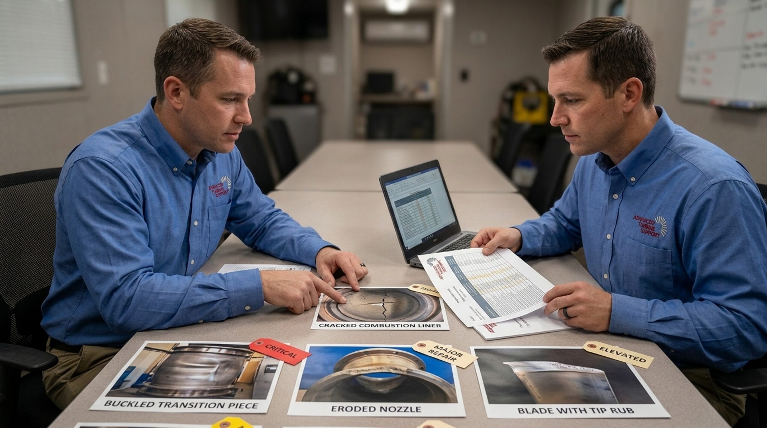
How Do Damage Patterns Compare Across Components, Cause, Severity, and Action
Damage Pattern Comparison Table
| Damage Pattern | Likely Cause | Severity Indicator | Recommended Action |
|---|---|---|---|
| Liner circumferential cracking | DLN combustion dynamics, thermal cycling | Crack length and depth relative to liner wall | Evaluate for braze repair vs. replacement |
| Transition piece cold-side seal cracking | Thermal gradient, spray angle deviation | Crack propagation toward hot side | Monitor or repair before next major outage |
| Nozzle leading-edge fatigue cracking | Thermo-mechanical fatigue, start/stop cycling | Crack density and orientation | NDT confirmation, repair or replace based on depth |
| Vane trailing edge erosion | Particulate ingestion, gas flow velocity | Material loss vs. design tolerance | Recoat or replace based on remaining thickness |
| Blade tip rub | Clearance loss, rotor dynamics | Rub depth and shroud contact pattern | Dimensional inspection, clearance correction |
| Blade TBC spallation | Coating debond, thermal cycling | Percent of exposed base alloy | Recoat or replace depending on oxidation extent |
Why Patterns Correlate Across Components
A liner hot streak rarely stays contained to the liner. It often lines up with sulfidation on the nearby first-stage nozzle, and eventually, tip rub or coating wear on the matching blade row. A repeated finding across the combustion liner, transition piece, and first-stage nozzle on the same unit is a strong sign of a combustion dynamics or fuel quality problem upstream, not five unrelated part failures.
Reading component life and projected service life together, rather than one part at a time, is what reveals whether compressor discharge air, fuel nozzle condition, or exhaust temperature spread is the real driver behind repeated turbine component distress. If your team is seeing the same pattern crop up across two or three components in the same outage, it’s worth walking through the findings with someone who inspects fleets like this regularly, rather than treating each part as its own isolated case.
Why Do NDT Methods and Clear Reporting Matter for Repair Decisions
Borescope images tell you where to look closer. They rarely tell you enough on their own to finalize a repair decision.
A reliability team at an independent power producer once flagged a liner hot streak during a routine borescope check and assumed it was isolated wear. When the finding was cross-referenced against the adjacent nozzle and blade row during the next scheduled inspection, sulfidation and early tip rub turned up in the same clock position. The pattern pointed back to a drifting fuel nozzle spray angle rather than three unrelated problems. Correcting the nozzle during the next outage resolved all three findings at once, instead of three separate repair cycles. Where blade tip wear had already progressed, turbine blade blending services restored the affected airfoils without a full replacement.
NDT Methods That Confirm What Borescope Images Suggest
Fluorescent penetrant inspection, sometimes called dye penetrant testing, reveals surface-breaking defects invisible to the naked eye. It works by drawing a fluorescent dye into cracks, which then glow under UV light. Eddy current testing detects cracking below the surface without further disassembly. Ultrasonic (UT) testing measures wall thickness and internal flaw depth on liners and transition pieces.
These inspection methods, combined with metallurgical review where thermal fatigue and creep are hard to tell apart visually, are standard practice for confirming what a borescope suggests before committing to a repair. Referenced codes such as API 570 and ASME B31.1 provide the broader inspection framework many of these NDT practices align with.
What a Clear Inspection Report Should Include
We document every finding against specific component IDs and clock positions, so two reviewers looking at the same report reach the same conclusion. That consistency matters. Inconsistent interpretation between inspectors is one of the most common sources of wasted time during an outage.
Our inspection reports pair photo documentation with NDT results and metallurgical notes where relevant. This gives plant engineering teams a solid basis for component repairs, whether that means a targeted repair, a recoat, or replacement, and helps sequence repair work so the outage window stays as short as possible. Fast scheduling keeps that diagnostic step from stretching out the outage window, which is often the bigger cost driver than the repair itself.
Conclusion: Turning Inspection Findings Into Confident Outage Decisions
Damage patterns on combustion liners, transition pieces, nozzles, vanes, and blades speak a diagnostic language. They are not noise. Reading them accurately protects turbine performance, keeps outage schedules predictable, and helps you spend repair budgets wisely instead of defaulting to blanket replacement.
You now have a framework for what these patterns mean, but confirming what you’re looking at before committing capital to a repair, replace, or run decision is the responsible next step, not an overcautious one. If you have borescope images or a recent HGPI report you’d like a second read on, call (352) 332-4061 or schedule a consultation with our team.
FAQ – Gas Turbine Hot Gas Path Damage Patterns
What causes cracking in combustion liners?
Combustion liner cracking is most often caused by DLN combustion dynamics, sustained thermal cycling, and fuel nozzle spray deviation that concentrates heat unevenly across the liner surface. Circumferential and axial cracks form differently depending on which stress dominates. Determining actual severity requires trained visual assessment paired with NDT confirmation, not a guess based on appearance alone.
How often should hot gas path inspections be performed?
Hot gas path inspections are typically scheduled based on OEM-recommended fired-hour and start-based intervals. These vary by frame type and DLN configuration across GE, Siemens Energy, and large Power turbine models. Duty cycle, fuel type, and number of starts all shift the practical interval. Actual timing should be confirmed with a qualified inspection provider familiar with your fleet’s operating profile.
What is the difference between a hot gas path inspection and a major overhaul?
A hot gas path inspection involves partial disassembly focused on the combustion and turbine sections, often guided by borescope inspection findings to target specific areas. A major overhaul involves full disassembly, including the compressor and exhaust sections, for complete condition assessment. A professional review of prior inspection findings determines which scope is actually needed at a given outage.
What does TBC spallation indicate on turbine blades?
TBC spallation means the thermal barrier coating has locally come loose from the blade’s alloy base, exposing base metal to direct combustion gas temperatures. This speeds up oxidation at the exposed area and reduces remaining blade life if left unaddressed. The extent of exposure should be measured by a technician using proper inspection tools, not estimated by eye.
How do you tell thermal fatigue from creep damage on nozzles?
Thermal fatigue on nozzles usually shows up as fine, multidirectional cracking at high-stress zones, while creep damage shows up as gradual dimensional change and bowing under sustained load. The two mechanisms produce different crack patterns under close examination. Metallurgical review remains the most reliable way to confirm which mechanism is actually driving a given finding.
What are common causes of transition piece distress?
Transition piece distress commonly comes from thermal gradient mismatch, fuel-nozzle spray angle deviation, and compressor discharge air maldistribution that reduces cooling in specific zones. Any one of these can cause cracking, buckling, or coating loss depending on severity and duration. Confirming the actual root cause usually requires comparing findings across multiple components, which is best handled by an experienced diagnostics team.
How often should a gas turbine borescope inspection be performed?
Borescope inspections are generally done more often and with far less disassembly than a full hot gas path inspection. They often serve as an interim check between major outages, letting engineers track how a known finding, like a liner hot streak, is progressing between scheduled teardowns. Scheduling should follow OEM guidance combined with a professional review of the unit’s actual operating history.
Can a cracked combustor liner be repaired or must it be replaced?
A cracked combustor liner can often be repaired through targeted weld or braze repair, as long as the crack depth and location fall within acceptable limits. Location relative to cooling holes, mounting points, and prior repair history all factor into that decision. Following established repair procedures and confirming results with NDT is what separates a lasting repair from one that fails prematurely. This call should never be made without professional evaluation and NDT confirmation, since a wrong judgment here carries real reliability risk. If you’re weighing that decision right now, a quick consultation can help confirm which direction actually makes sense for your unit.
Next Posts
Pre-Outage Borescope Inspection: How to Define Repair Scope Before the Turbine Comes Apart
admin September 25, 2026
OEM vs. Independent Borescope Inspection Providers: What Plant Managers Should Compare
admin September 11, 2026
GE 7EA Compressor Borescope Inspection: Common Failure Modes, TILs & What Operators Should Look For
admin August 28, 2026